rib design
Optimize the strength and efficiency of plastic parts with YUCO expert rib design. Learn the key principles for successful injection molding. Professional mold manufacturer in China.

Professional plastic parts ribs design for injection molding
A typical manufacturing process is called injection molding, which can produce a wide variety of plastic parts. Ribs are an important design factor that can make or break an injection molded part.
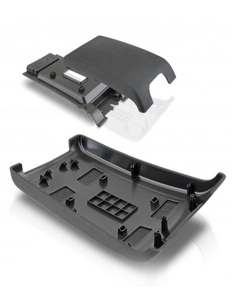
Ribs provide additional strength and support without increasing the weight or material consumption of the part. Ribs are typically thin and narrow, with their width significantly shorter than their length. They typically do the following:
- Increase the bending stiffness and strength of the part.
- Reduce warping and tilting.
- Improve the overall structural integrity of the part.
- Enhance the aesthetics of the part.
Ribs can be designed to be visible or hidden, depending on the application and desired appearance. Ribs are widely adaptable and can be used in almost any injection molded part, including:
- Consumer products (e.g., containers, daily necessities)
- Industrial parts (e.g., gears, brackets)
- Medical devices (e.g., instrument handles, implantable devices)
- Automotive parts (e.g., dashboards, trim)
types of ribs and their application
Plastic product's ribs come in various shapes, sizes, and designs, each with unique advantages and uses. Some common types of ribs are:
solid ribs
Solid ribs are the most common type of rib and feature a continuous, solid profile that provides maximum strength and stiffness and is easy to design and form. They are the first choice for high stress areas in load-bearing components and critical structural parts. However, solid ribs can lead to increased material usage and cooling issues in thick sections.
hollow ribs
Hollow ribs have a hollow or tubular cross-section that reduces material consumption and weight while maintaining strength. These ribs are best suited for lightweight structural parts as well as appearance parts. The hollow design strikes a balance between strength and efficiency, making it popular across industries.
straight ribs
Straight ribs are characterized by their simple linear design, making them easy to implement and manufacture. They provide uniform support along their length, making them ideal for reinforcing flat surfaces, reinforcing the stiffness of long, narrow parts, and supporting walls in box. Sidewall ribs are straight ribs and can be used to enhance vertical load-bearing capacity, such as support walls for plastic containers or crates.
curved ribs
Curved ribs have a curved or rounded profile that can follow contoured surfaces, they are able to conform to complex shapes while providing strong support. Curved ribs excel in applications involving curved or rounded product designs, such as curved structural parts (pipe fittings) and ergonomic handles or grips.
V-Ribs
V-ribs have a V-shaped cross-section that provides a strong and rigid structure. V-ribs achieve significant reinforcement while using less material than comparable solid ribs. This design is particularly effective for parts that require a high stiffness-to-weight ratio, such as aerospace components and high-performance automotive parts.
T-Ribs
T-ribs, characterized by their T-shaped cross-section, provide excellent stiffness in two directions. This makes them ideal for parts subject to multi-directional stresses, reinforcing joints or intersections, and structural components in furniture or building products. T-ribs allow for a wider support base while maintaining a thin profile, providing a good balance of strength and material usage.
grille ribs
Grille ribs consist of a series of parallel ribs that typically intersect to form a grid-like structure. This design is often used for ventilation grilles, speaker covers, and as an aesthetic feature for design-oriented products. Grille ribs not only provide structural support, but can also serve a functional purpose, such as allowing airflow or sound transmission, while maintaining strength and visual appeal.
guss ribs
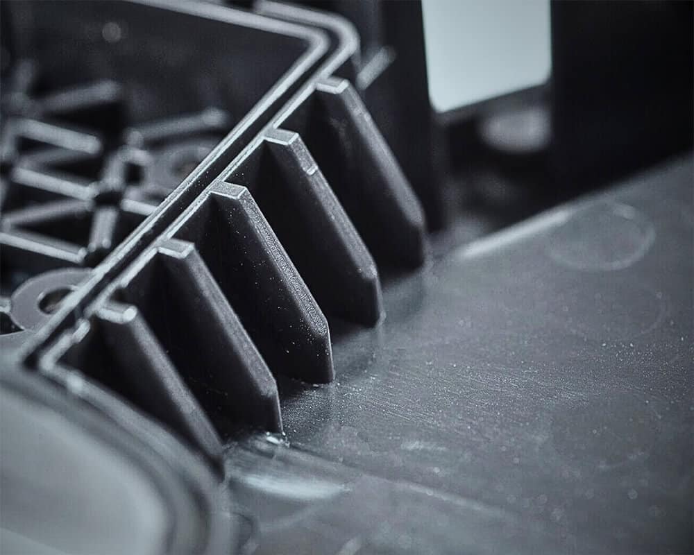
Guss ribs are triangular or trapezoidal ribs that are specifically placed at corners or edges to enhance the structural integrity of these potential weak points. Guss ribs provide improved resistance to torsion and bending and are particularly effective in distributing stress at joints and preventing deformation under load. They are best used to reinforce the corners of box-like structures, strengthen mounting points, and support protruding components.
Contact our plastic part ribs design team now!
Rib design considerations
When designing ribs for plastic injection molded parts, several key factors must be considered to ensure optimal performance, productivity, and cost-effectiveness. Here are some important design considerations:
Material selection
The choice of plastic material can significantly impact rib design. Different materials have different mechanical properties, shrinkage, and flow characteristics. The selected material must balance structural requirements, manufacturing constraints, and cost considerations. Factors to consider when selecting rib materials include:
- Strength and stiffness: Select materials with appropriate tensile strength, flexural strength, and elastic modulus. Stiffer materials such as polycarbonate (PC) or glass-filled polymers may require fewer or smaller ribs to achieve the same structural integrity compared to more flexible materials such as polyethylene.
- Impact resistance: For applications subject to stress, shock, or vibration, consider materials with high impact resistance.
- Chemical resistance: Select materials that are resistant to corrosion, chemicals, or environmental factors that may affect the performance of the part.
- Thermal properties: Consider materials with adequate thermal expansion, conductivity, and stability for applications with temperature changes.
- Shrinkage: Materials with high shrinkage, such as polyethylene (PE) or polypropylene (PP), may require thinner ribs to minimize sink marks. Conversely, materials with lower shrinkage, such as glass-filled nylon, can accommodate thicker ribs without worrying about surface defects.
- Material flow characteristics: Materials with high melt flow indexes may allow for more complex rib patterns, while materials with lower flow rates may require simpler, more widely spaced rib designs to ensure proper mold filling.
rib shape
The selection of rib shape should be based on the specific structural requirements of the part, the forces that will be encountered in service, and manufacturing considerations of the selected material and molding process. Straight ribs are most common due to their simplicity and effectiveness.
Curved ribs can provide excellent strength for parts with complex geometries or those subject to torsional forces. Tapered ribs decrease in thickness from base to tip, helping to reduce sink marks while maintaining structural integrity. X-shaped or cross-rib designs can provide multi-directional strength in areas subject to different stress patterns. Triangular ribs can be used to reinforce corners, providing additional strength.
rib thickness
Determining the optimal rib thickness is critical to balancing part strength, manufacturability, and surface quality. Common rib sizes are as follows:
- Thin ribs (0.5-1.0 mm): For small parts, precision applications, and delicate structures
- Thick ribs (1.5-2.0 mm): For large parts, high-pressure applications, and structural parts
Thicker ribs provide greater strength but increase the risk of sink marks and may require longer cooling times. Conversely, thinner ribs reduce the risk of surface defects but may not provide adequate structural support.
Generally, rib thickness should be 50-60% of the nominal wall thickness of the part, which is typically 0.5-2.0 mm (0.02-0.08 in). This ratio helps minimize sink marks while still providing important structural support. For example, if the primary wall thickness is 2 mm, the rib thickness should ideally be between 1-1.2 mm. However, this rule may need to be adjusted based on specific material properties and part requirements.
Also note that rib thickness may need to vary within a single part. Areas subject to higher stresses may require thicker ribs, while less critical areas can use thinner ribs to minimize material usage and cycle time.
rib height
Rib height plays a critical role in determining part stiffness. Generally, taller ribs provide greater stiffness, but there are practical limits to consider.
- Small parts: 0.5-1.5 mm (0.02-0.06 in)
- Medium parts: 1.5-3.0 mm (0.06-0.12 in)
- Large parts: 3.0-5.0 mm (0.12-0.2 in)
The optimal height-to-thickness ratio for ribs is typically between 2.5 and 3 times the part wall thickness. For example, if the wall thickness is 2 mm, the rib height might be between 5 mm and 6 mm. However, this ratio can be adjusted based on specific part requirements and material properties.
It is important to note that as rib height increases, the risk of warpage and molding difficulties also increases. Very tall ribs can be prone to bending or buckling under load, and they can also present challenges with mold filling and cooling.
In some cases, it may be more effective to use multiple shorter ribs rather than a single taller rib. This approach can provide similar stiffness while reducing the risks associated with very tall ribs.
rib spacing
The spacing between ribs is another critical factor in rib design. Proper rib spacing ensures:
- Even stress and load distribution
- Excellent structural integrity
- Minimal warpage and shrinkage
- Improved formability and manufacturing efficiency
The distance between ribs should be 2 to 3 times the rib width. For example:
- Narrow spacing (2-3 mm): for high-pressure applications, structural parts and small parts
- Wide spacing (4-5 mm): for large parts, decorative parts and low-stress applications
Factors that influence rib placement
- Material properties (shrinkage, warpage, strength)
- Part size and complexity
- Structural requirements (stress, load, impact)
- Mold design and manufacturing constraints
Ensure adequate spacing to avoid material accumulation and mold filling issues. When ribs are spaced too close together, it may cause sink marks on the other side of the part. This is because ribs that are too closely spaced cool more slowly than the surrounding area, resulting in uneven shrinkage. Conversely, ribs that are too far apart may not provide adequate structural support, which may cause part failure or excessive deflection under load. It is important to space the ribs as evenly as possible on the part. Even distribution helps balance cooling rates and internal stresses, reducing the likelihood of warping.
draft angle
Draft angle is an important consideration in injection molded rib design. The draft angle refers to the taper of the rib to allow for easy release from the mold. Proper draft angle ensures:
- Smooth demolding
- Less risk of rib breakage or damage
- Improved part quality and surface finish
- Improved manufacturing efficiency
Draft angle guidelines
- Minimum draft angle: 1-2 degrees (0.5-1.0 mm/0.02-0.04 in. per 10 mm/0.4 in. rib height)
- Recommended draft angle: 2-3 degrees (1.0-1.5 mm/0.04-0.06 in. per 10 mm/0.4 in. rib height)
- Maximum draft angle: 5 degrees (2.5 mm/0.1 in. per 10 mm/0.4 in. rib height)
Factors affecting draft angle
- Rib height and width
- Material shrinkage and mold shrinkage
- Part complexity and mold design
- Injection system and mold type
Insufficient draft can cause the part to stick in the mold, causing damage during demolding or increasing cycle time. On the other hand, over-drafting can reduce the structural effectiveness of the ribs and may affect part aesthetics.
It is important to note that the draft angle should be applied to all surfaces parallel to the mold opening direction, not just the ribs. Consistently applying draft throughout the part design process helps ensure smooth demolding and reduces the risk of part distortion.
rib bottom radius
The rib bottom radius is a critical feature of rib design that is often overlooked. The radius where the rib meets the main wall of the part is critical to reducing stress concentrations and preventing part failure.
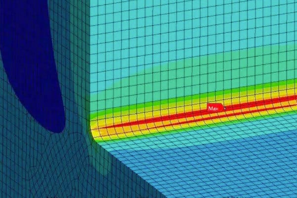
The sharp corners at the base of the rib create areas of high stress concentration, which can cause cracks to initiate and propagate under load. By incorporating a radius at this intersection, stress distribution is more even, reducing the risk of part failure.
The bottom radius should be approximately 25-50% of the wall thickness. For example, if the wall thickness is 2 mm, the bottom radius should be between 0.5 mm and 1 mm.
Larger radii provide better stress distribution but increase the risk of dents. Smaller radii are less likely to cause dents but provide less stress relief. The optimal radius often depends on the specific material properties of the part and the loading conditions.
sharp corners
Similar to the base radius, sharp corners are important to reduce stress concentrations throughout the rib design. Sharp corners, whether internal or external, can cause cracking and fracture or cause material structure and mold filling issues.
Corners can be filled with a radius of at least 0.5 mm (0.02 in), but larger radii are generally preferred if space permits. The radius of internal corners should be as large as possible, and a radius of at least 1 mm (0.04 in) is generally used. Chamfers can also be used, with an angle of 45 degrees and a width of at least 0.5 mm (0.02 in).
When designing corners, consider:
- Material properties (strength, stiffness, impact resistance)
- Rib size and shape
- Local activation and stress concentrations
- Mold design and manufacturing constraints.
Finite element analysis (FEA) can be a useful tool for optimizing fillet radii for specific loading conditions.
connections to walls and corners
How ribs connect to walls and corners is critical to both part strength and aesthetics. Abrupt transitions create stress concentrations and disrupt material flow during molding. Smooth, gradual changes in geometry not only improve structural performance but also enhance the overall appearance of the part.
For wall connections, gradual transitions are best. This can be accomplished by gradually decreasing the height of the rib as it approaches the wall, or by using a larger radius at the connection.
When connecting ribs at corners, care must be taken to avoid creating thick sections that can cause sink marks or long cooling times. One approach is to stop the ribs at the corners and use gusset-like features to connect them together. Another approach is to alternate the height of intersecting ribs to maintain a more consistent material thickness.
common rib design problems and solutions
While ribs are critical to structural integrity in plastic injection molding, they can sometimes present their own set of challenges. Let’s explore some of the most common issues encountered with rib design and how to effectively address them.
Sink marks
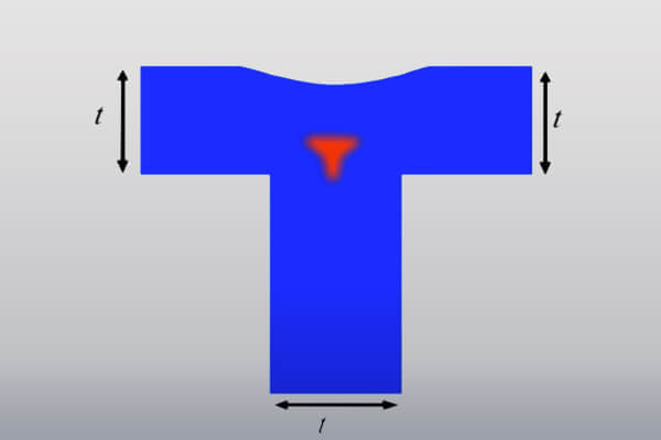
Sink marks, also known as sink marks, are one of the most common problems associated with rib designs. These surface depressions appear on the opposite side of where the rib is located. Sink marks are primarily caused by uneven cooling rates between the thicker rib section and the surrounding thinner area. As the rib sections cool and shrink more slowly, they pull material from the surface, creating visible sink marks.
solutions to reduce sink marks
- Adjust rib thickness. Rib thickness should be 50-60% of nominal wall thickness.
- Increase cooling time. Longer cooling time helps equalize shrinkage across different parts.
- Using hollow ribs reduces the overall mass of the rib, which promotes more even cooling.
- Using textures or patterns can help mask minor sink marks and make them less noticeable.
- Consider alternative materials. Using certain filler materials or materials with lower shrinkage may be less prone to sink marks.
Warpage
Warpage is another significant issue that can result from improper rib design. This occurs when different parts of a part cool at different rates or experience uneven internal stresses. Ribs are designed to prevent warpage, but can also cause it if not designed correctly.
Ways to fix warpage
- Ensure ribs are placed as symmetrically as possible on both sides of the part.
- Use mold flow analysis tools to predict and visualize potential warpage before production begins.
- Optimize gate locations for more uniform filling and cooling patterns.
- Align ribs with the direction of material flow to minimize flow resistance and reduce internal stresses.
- Fine-tune injection pressure, holding pressure, and cooling time to minimize warpage.
- Maintain consistent wall thickness throughout the part as much as possible to promote uniform cooling.

Stress concentrations
Sharp corners or abrupt transitions in rib designs can cause stress concentrations, which are areas where stress is amplified. These concentrations can cause part failure, especially under load or impact.
Alleviate stress concentrations
- Add fillets and radii to corners to reduce stress concentrations and improve moldability. For example, use a radius of about 25-50% of the wall thickness.
- Gradually reduce the height of the rib ends to help distribute stress more evenly.
- Where ribs meet, use appropriate radii and avoid sharp corners to minimize stress concentrations.
- Make gradual transitions between different thicknesses to prevent stress buildup.
- Use simulation tools to identify potential stress hotspots and optimize the design accordingly.
Flow marks
Flow marks can occur when ribs disrupt the smooth flow of molten plastic during injection. These marks appear as wavy lines or patterns on the surface of the part, affecting its appearance.
minimize flow marks
- Position ribs to follow the natural flow of material in the mold, rather than against it.
- Adjust rib height and thickness; lower, thinner ribs are less likely to significantly disrupt material flow.
- Increasing the injection speed can help the material maintain temperature and flow more smoothly over the ribs.
- Consider material selection; some materials are less prone to flow marks than others.
Weak points
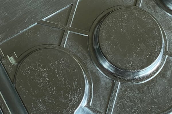
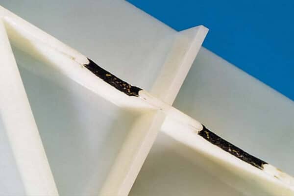
Poorly designed ribs can sometimes create weak points in a part, especially where ribs intersect or where the ribs meet the wall.
Ways to address weak points
- Use gussets at intersections to strengthen rib connections.
- Implement gradual transitions to avoid sudden changes in rib height or thickness, especially where the ribs meet the wall.
- Consider load paths so that ribs effectively transfer expected loads into the part.
- Use FEA to identify weak areas and pinpoint potential failure points before production.
Optimize your products with expert rib design and injection molding
Are you looking to improve the performance, quality, and cost-effectiveness of your plastic products? As a leading injection mold manufacturer in China, YUCO specializes in optimizing rib design and producing high-quality injection molds for a wide range of industries.
Why choose us?
- Our experienced team of engineers can help you fine-tune your rib design for maximum strength, minimal material usage, and optimal manufacturability.
- We utilize innovative technology to produce precision molds, ensuring consistent, high-quality parts.
- Our in-depth knowledge of a wide range of plastic materials enables us to recommend the best options for your specific application.
- From concept to final product, we offer fast turnaround times to meet your project deadlines.
Whether you are looking to start a new injection molding project or optimize an existing design, we are here to help. Contact us today to discuss how we can help you achieve superior plastic parts with expert rib design and precision injection molding.
Tel: +86 13586040750