undercut design
Explore the crucial role of undercuts design in plastic part. Learn about YUCO innovative techniques, design considerations, and expert services for optimal performance.

Professional undercuts design for plastic part in China
While critical to functionality and aesthetics, injection molding undercuts can involve complex shapes and designs that prevent the part from being removed from the mold without damage. These features also typically increase the overall complexity and associated costs of the plastic part, so it is best to avoid them whenever possible.
But what if these challenges could be turned into opportunities for innovation and competitive advantage? As a leading professional injection molding service provider in China, YUCO MOLD understands that undercuts are not an obstacle to be avoided, but a powerful tool for manufacturing quality plastic parts.
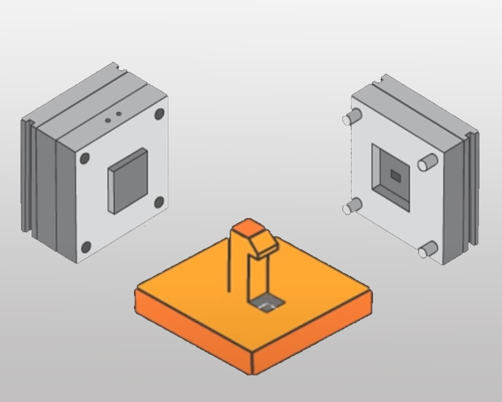
Understanding undercut
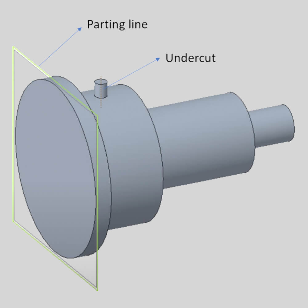
Undercut is a recessed feature or area in a molded part that prevents the part from ejecting straight out of the mold in the direction the mold opens. In short, it is any feature that creates a snag or “overhang” that prevents the part from being removed from a simple two-part mold.
There are times when undercuts are necessary. Because these features are so critical to the function of the part that they cannot be avoided. Here are five of the most common situations where undercut injection molding is necessary.
- Interlocking features: Snaps, latch features, or any similar features allow for easy assembly and operation.
- Side holes: This is more common in consumer electronics, but is not specific to this field. Access points, ports, and buttons can be added to housing units through side holes.
- Barbed connectors: Barbed connectors are one of the most common components used for airflow control.
- Vertical threads: Essential for a secure connection to withstand light loads and pressure on a variety of connectors, hoses, and other components.
- Custom inserts: Any custom feature that requires a specific design element that cannot be paralleled with a molded stretch.
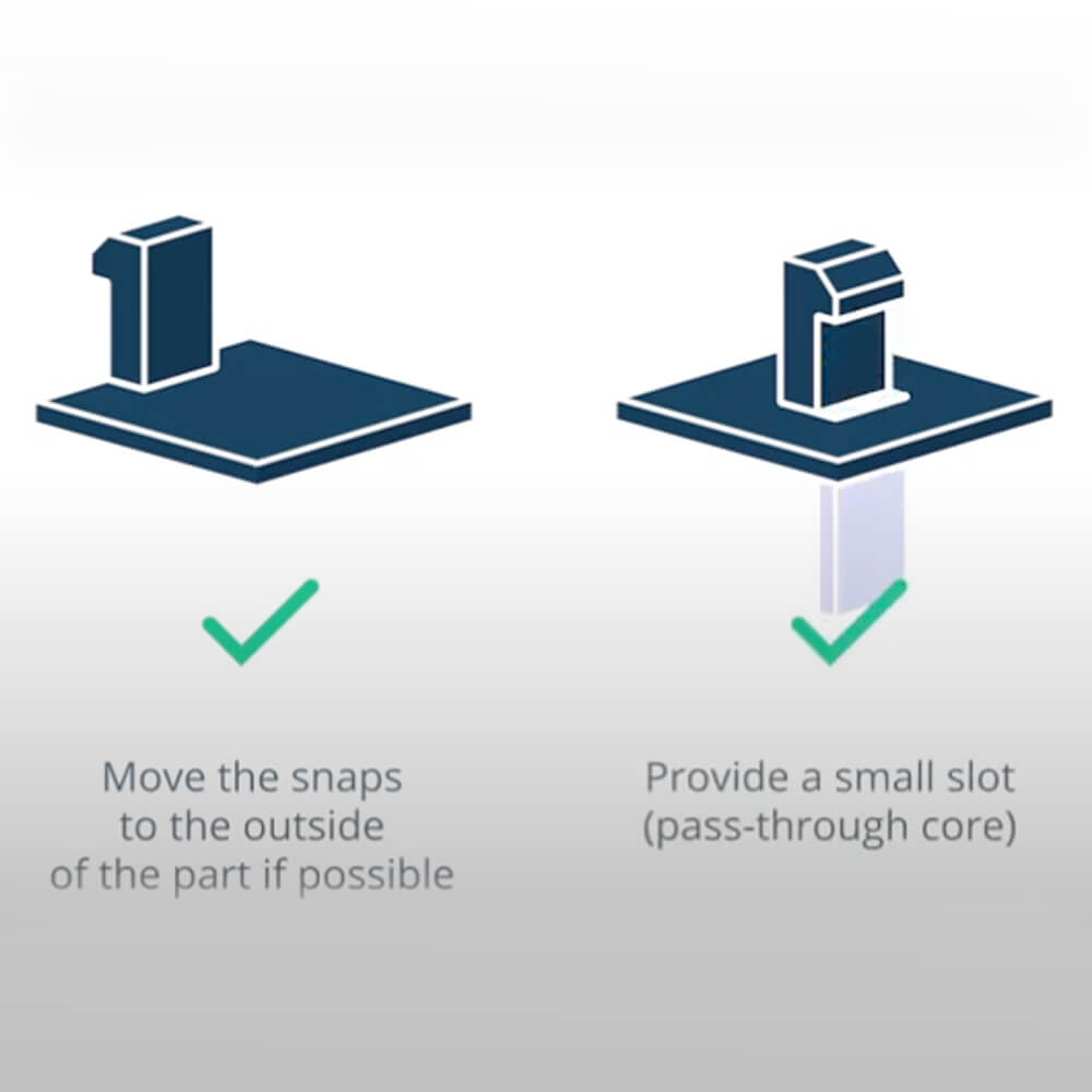
In plastic parts, undercuts serve several key functions. They can create more innovative, functional, and aesthetically pleasing plastic parts, while also providing a reference for selecting appropriate manufacturing methods and design optimization.
- Functional features: Undercuts often constitute the basic functional elements of a part, such as snaps, hooks, or internal threads. These features enable parts to connect, lock, or interact with other components in an assembly.
- Aesthetic design: Undercuts can increase the visual appeal of a part, creating depth, texture, or a unique shape.
- Structural integrity: In some cases, undercuts can be used to reinforce parts, creating a stronger, more durable design without increasing overall material usage.
- Assembly efficiency: Undercuts can make the assembly process easier or safer, reducing the need for additional fasteners or connection methods.
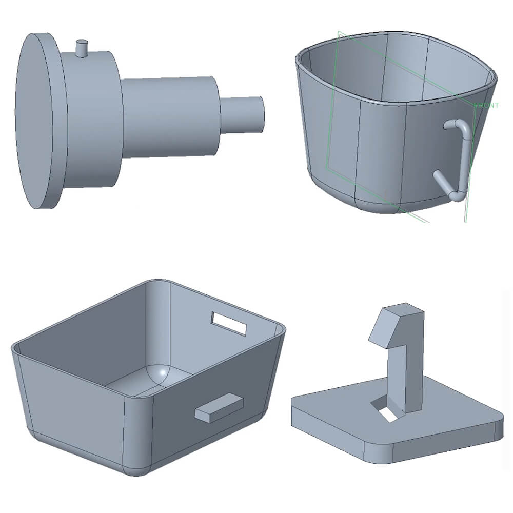
There are three main types of undercuts in plastic parts: internal, external, and compound. Each type offers unique design opportunities and manufacturing challenges.
An internal undercut is a recessed feature located inside a part, usually facing away from the mold's parting line.
- Internal threads in bottle caps or screw fittings
- Holes or cavities with protruding features
- Internal grooves for O-ring seals
External undercuts are protruding features on the outside surface of a part that prevent straight-line removal from the mold.
- Snap-on hooks or latches
- Lips or flanges on containers
- External grooves for gaskets or decorative purposes
Compound undercuts involve a combination of internal and external undercut features on the same part.
- Bottles with internal threaded necks and external gripping features
- Electronic housings with internal mounting bosses and external snaps
- Automotive parts with internal cooling channels and external connection points
Contact YUCO injection molding undercut design team now!
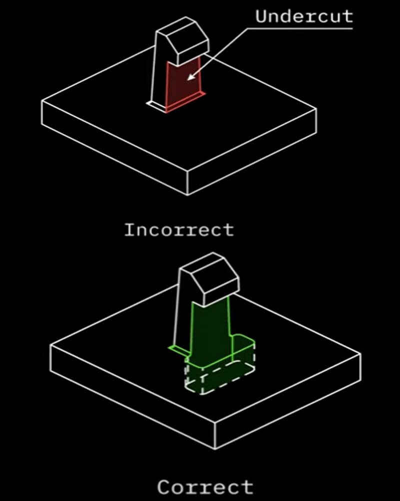
Design considerations for parts with undercuts
When designing parts with undercuts, several key factors must be considered to ensure successful molding and optimal part performance. Here are the key design considerations:
Material selection
Material selection has a significant impact on the design and manufacturability of parts with undercuts. More flexible materials can demold undercuts more easily. Materials with higher shrinkage may require larger undercuts to maintain final dimensions. Stronger materials can achieve more aggressive undercuts without causing part damage during demolding
Additionally, the overall elasticity and flexibility of the material you choose determines the solutions you can use to improve your undercut molding.
Draft angle
Draft angle is critical to facilitate the release of undercut parts from the mold. Proper draft angle reduces friction when ejecting the part, minimizing the risk of part deformation or damage. It also allows the material to flow more easily during the molding process.
Optimal draft angle recommendations for different undercut types:
- External undercuts: minimum draft angle 3°, preferably 5° or more
- Internal undercuts: minimum draft angle 1°, preferably 2° or more
- Deep undercuts: may require up to 10° or more draft angle
- Textured surfaces: add an additional 1-2° draft angle to account for texture depth
wall thickness
Proper wall thickness design is critical for parts with undercuts to ensure structural integrity and formability. Maintain uniform wall thickness around undercuts (minimum wall thickness 0.5 mm (0.020 in)) to promote uniform cooling and reduce warpage. Use gradual thickness changes to avoid stress concentrations.
corner radius
Proper corner radius design can significantly impact the success rate of molding parts with undercuts. Larger radii can help direct material flow around undercuts, dissipating stress and preventing part failure during demolding. Fillets reduce the effective depth of undercuts, making demolding easier. For most applications, strive for a minimum radius of 0.5 mm (0.020 in.)
undercut depth and angle
Undercuts directly impact moldability and part functionality. Keep undercut depth to less than 30% of the overall part size and require undercut angles less than 90° for easy demolding. For snap-fit features, consider using a sloped entry angle and a steeper return angle
Gating and venting
Proper gating and venting are critical for parts with undercuts to ensure complete filling and air evacuation.
Strategically place gates to promote uniform material flow around undercuts. For complex parts with multiple undercuts, consider using multiple gates
Ensure adequate venting in deep undercut areas and sometimes use vacuum venting to address challenging undercut geometries
Methods to solve undercut molding designs
Undercuts present unique challenges in plastic part design and manufacturing. However, several methods have been developed to effectively address these challenges. The following six methods can help you effectively solve undercut molding designs. By carefully considering these methods and their implications, you can create complex parts with undercuts while maintaining efficiency and quality in the production process.
Location of dividing lines
One of the simplest ways to solve undercuts is to strategically locate the dividing line (also known as the parting line) of the mold. The dividing line is the intersection plane between the two molds. By placing the dividing line on the protruding feature, you can avoid undercut problems. When the feature is divided into two parts by the dividing line, the part can be removed from the mold without adding undercuts.
Advantages
- Can simplify mold design
- Can reduce or eliminate the need for complex mechanisms
Considerations:
- May cause visible parting lines on the finished part
- Not always possible, depending on the geometry of the part
Lateral action/cam action
When undercuts are required, side action, also known as cam action, can help keep the part functioning as intended. A side core is an insert that exits the part during the injection process.
As the material is extruded, it cannot fill the volume occupied by this insert. Once the molding process is complete, the insert is ejected, leaving behind an undercut.
Advantages:
- Can create complex external undercuts
- Allows automated production
Considerations:
- Adds mold complexity and cost
- May require longer cycle times
- Requires careful maintenance to ensure proper operation
Using a bump off
If you are working with flexible materials, a bump off is an excellent choice. The process works just like a typical injection molding job, except an insert is added. Once the process is complete, this insert is removed first. This space leaves "play room" for the part. Because there is a hollow space within the mold, the part can deform slightly, allowing it to exit the mold without damage.
While a bump off may seem easy. There are several factors to consider when using bump offs. Here are some basic limitations when using a bump off for undercut molding:
- The part should be flexible enough to be pinned without damage.
- Rigid features such as corners and ribs should be avoided.
Lifters and ejector pins
Lifters and specialized ejector pins can be used to create and release certain types of undercuts.
Advantages
- Can handle both internal and external undercuts
- Integrates into ejection system for increased efficiency
Considerations
- Limited complexity of undercuts that can be handled
- May leave marks on finished product
- Requires precise design and setup
Manual loading and insertion
As the name implies, they are manual techniques performed by a technician. Manual loading of core pins or inserts may be necessary for low volume production or extremely complex undercuts. They are not automated and are typically used for internal undercut injection molding jobs or designs that cannot be completed by any other means.
A manually loaded insert is a metal piece that the operator manually places into the mold to prevent plastic from flowing out. This simplifies the extrusion process because the operator can remove the piece after the cycle is complete and reuse it for the next batch.
Advantages:
- Allows creation of virtually any undercut geometry
- Good for prototypes or low volume production
Considerations:
- Labor intensive and time consuming
- Not suitable for high volume production
- Human error and inconsistency possible
Shut-offs
A shut-off is a temporary barrier that uses a hook, clip, or similar component to snap into a specific area of the design and block flow. However, you must modify your design to use this technique effectively. Make sure your design has adequate draft angles to facilitate a problem-free ejection process.
Advantages:
- Can create precise, clean undercut features
- Applicable to both internal and external undercuts
Considerations:
- Increases mold complexity and cost
- Requires careful design and maintenance
- May affect cycle time
Industry applications of undercuts
Undercuts are widely used in various industries to create functional and innovative product designs. Here are some industry applications where YUCO MOLD has successfully implemented undercuts:
Consumer electronics

The consumer electronics industry often utilizes undercuts to create stylish, functional designs. Most consumer electronics rely on plastic housings because they are durable, long-lasting, insulating, and affordable. However, plastic housings require multiple undercuts to access the inner housing or for users to add buttons, switches, and other elements.
YUCO project example: Smartphone housing
- Undercut snap-on features allow for easy assembly and disassembly
- Precise undercuts create tight-fitting openings for buttons, ports, and camera lenses
- Materials such as polycarbonate (PC) or thermoplastic polyurethane (TPU) are often used for their flexibility and durability
Medical devices
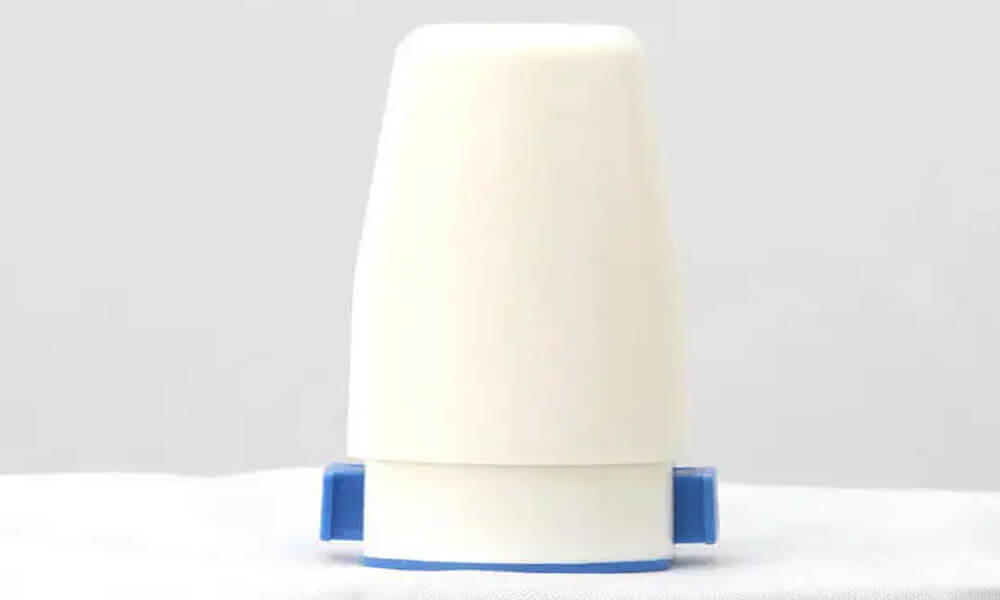
Medical plastic parts are often manufactured using undercut plastic injection molding processes because most designs in this industry are designed to handle complex tasks. In such applications, a variety of undercut molding techniques can help designers ensure optimal performance without compromising the overall effect of a specific part.
YUCO project example: Inhaler devices
- Undercuts create an airtight seal and precise dosing mechanism
- Snap-on components allow for easy removal for cleaning or replacement
- Materials such as medical-grade polypropylene are widely used for their chemical resistance and biocompatibility
Packaging industry
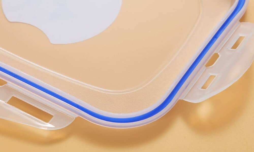
Undercuts are essential for creating functional and user-friendly packaging solutions.
YUCO project example: Food containers
- Undercuts create an airtight seal between container and lid
- Snap-on feature allows for easy opening and closing
- Materials such as polypropylene are used for their durability and food-safe properties
The role of YUCO's undercut design capabilities in part performance
Well-designed undercuts can enable parts to provide excellent performance, assembly efficiency and user experience. At YUCO MOLD, we focus on optimizing undercut features for optimal performance and manufacturability. We maintain open communication throughout the design process. To stay at the forefront of undercut design and manufacturing, we use a range of advanced technologies and processes:
- For complex undercuts, use multi-shot or overmolding technology for efficient production.
- Our mold design uses conformal cooling channels to optimize the cooling process of parts with challenging undercut features.
- We utilize advanced sliding core and lifter designs to achieve complex undercuts.
- Using advanced mold flow analysis and structural simulation software
- We utilize high-resolution 3D printing to quickly prototype and test undercut designs.
Don’t let the complexity of undercut design hold you back from your product. Contact us today.
Tel: +86 13586040750