wall thickness design
Advanced wall thickness design from YUCO, the Chinese injection molding expert. Work with YUCO to get high-quality parts and innovative solutions for injection molds.

Professional injection molding wall thickness design in China
Injection molding is a popular manufacturing technique that allows for mass production of plastic parts with high efficiency and precision. At the heart of successful injection molding lies a critical but often underestimated factor: wall thickness design. Wall thickness refers to the distance between the two surfaces of a molded part and plays a key role in determining the feasibility of production as well as the quality, functionality, and overall performance of the final product.
It affects everything from the flow of molten plastic within the mold to the structural integrity of the finished part, such as material flow, cooling time, structural integrity, and overall production costs
As experts in this field, YUCO has encountered many challenges arising from suboptimal wall thickness design. These experiences have strengthened our commitment to precision engineering and comprehensive design analysis at every stage of the injection molding process.
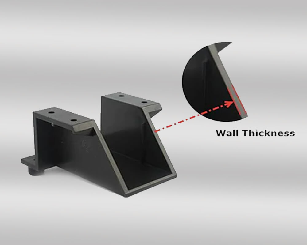
importance of wall thickness in injection molding
Wall thickness is an important parameter in the design and production of injection molded parts. Engineers, designers, and manufacturers who wish to create high-quality, affordable plastic parts must understand its importance and how it affects the overall quality, performance, and manufacturability of the final product.
material flow
One of the main reasons for wall thickness is that it affects material flow and the ability of molten plastic to fill the mold. This is critical because:
During the injection molding process, molten plastic is injected into the mold at high pressure. If the wall thickness is too thin, the material cannot flow properly, resulting in incomplete fill, especially in complex geometries or details. In addition, thinner walls may require higher injection pressures, but may cause other problems.
Conversely, thicker walls can make flow easier, but may result in wasted material or uneven cooling. Constant wall thickness ensures uniform flow and reduces the risk of flow-related defects such as short shots (incomplete parts) and weld lines (lines that show where the flow fronts meet).
cooling time and cycle efficiency
Wall thickness directly affects cooling time, which in turn affects the overall cycle time and productivity of the injection molding process:
- Thicker walls require longer cooling times, longer cycle times, lower output, and increased costs.
- Thinner walls require faster cooling, shorter cycle times and higher productivity.
- Uneven wall thickness can lead to differential cooling, causing part warpage or internal stress, while internal stress and warpage can compromise the dimensional accuracy and structural integrity of the part.
Optimizing wall thickness for efficient cooling while maintaining part quality is a delicate balance that requires YUCO’s expertise.
structural integrity and performance
The structural integrity and mechanical properties of injection molded parts are affected by wall thickness, including:
- Strength and stability: Adequate wall thickness is necessary to provide the strength and stability required for the part's intended use. Parts with insufficient wall thickness may fail under load or stress, resulting in product failure and potential safety issues. Thicker walls provide greater strength and stiffness, but at the expense of increased weight and material cost.
- Impact resistance: Thicker walls make parts more impact-resistant and less susceptible to damage during handling, assembly, or use. This is especially important for parts that are subject to high stress or impact in operating environments. Thin walls can reduce weight and material usage but may affect the part's ability to withstand load or impact.
Our experience shows that proper wall thickness design ensures that parts meet performance requirements without unnecessary material waste.
Dimensional stability and tolerance control
Maintaining consistent wall thickness throughout a part is critical for dimensional stability. When wall thickness is inconsistent, achieving tight tolerances becomes more challenging.
- Shrinkage control: Uniform wall thickness helps plastic materials achieve consistent shrinkage, reducing the potential for dimensional variation and ensuring parts meet specified tolerances.
- Warp prevention: Uniform wall thickness reduces the risk of warping, ensuring parts maintain the desired shape and size.
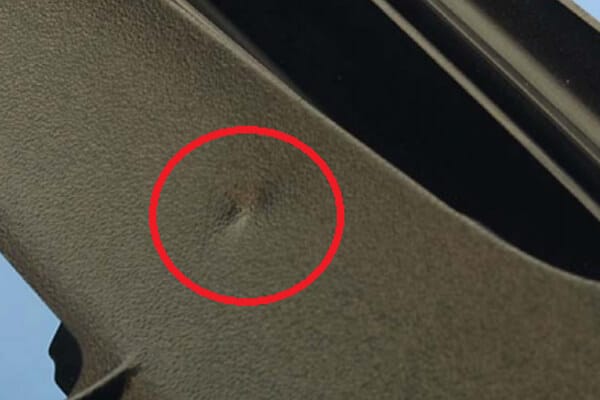
- Surface defects: Uneven wall thickness can lead to surface defects such as sink marks and internal cavities. These defects not only affect the appearance of the part, but also undermine its structural integrity.
- Surface finish and texture: Uniform wall thickness helps achieve consistent surface finish and texture, which is critical for parts that require high aesthetic standards.
manufacturing costs
Wall thickness directly impacts manufacturing costs in several ways:
- Material use: The thicker the wall, the more material is required, which increases raw material costs and affects total production costs.
- Cycle time: As mentioned earlier, the thicker the wall, the longer it takes to cool, which reduces production efficiency and increases labor and machine time costs.
- Energy consumption: The higher injection pressures required for thin-walled parts increase energy costs.
- Mold complexity: Designs with varying wall thicknesses may require more complex and expensive molds.
- Scrap rates: Improper wall thickness design can result in higher defect rates, increasing waste and overall production costs.
By optimizing wall thickness, YUCO can help customers minimize manufacturing costs while maintaining product quality and performance.
Contact our injection molding wall thickness design team now!
Designing for optimal wall thickness
Designing parts with optimal wall thickness is essential to achieving high-quality, cost-effective injection molded products. Here, YUCO provides comprehensive advice and best practices on creating sections with ideal wall thickness.
material properties
Different plastics have different flow characteristics, cooling rates, and shrinkage characteristics. Understanding material properties is critical to determining optimal wall thickness.
- Flow properties: Resins with high melt flow rates, such as polypropylene, can fill thinner walls more easily than resins with lower melt flow rates, such as certain high-temperature thermoplastics. This is often measured by the melt flow index (MFI).
- Crystallinity: Semicrystalline polymers, such as nylon or polyethylene, shrink more than amorphous polymers, such as ABS or polycarbonate, influencing wall thickness decisions to maintain dimensional stability.
Standard wall thickness ranges for common materials:
- ABS, PC, PS: These materials typically require slightly thicker walls (2-4 mm) due to their high viscosity and low shrinkage.
- PP, PE, PA: These materials can have thinner walls (1.5-3 mm) because they flow faster and shrink more.
Specific applications may need to be adjusted based on other factors.
Part geometry and complexity
Part size, shape, and complexity can significantly impact wall thickness decisions. When designing injection molded parts, following these best practices can help achieve optimal wall thickness:
- Part size: Larger parts require thicker walls to maintain structural integrity and facilitate uniform fill.
- Shape complexity: Complex shapes with multiple curves or angles may require varying wall thicknesses to ensure proper flow and prevent defects.
- Ribs and bosses: Ribs and bosses provide additional strength and stiffness to thin-walled parts. Ribs should be 50-70% of the nominal wall thickness, while bosses should be up to 60% thick. These features help strengthen the section without significantly increasing the overall wall thickness, while minimizing material consumption.
- Corners and radiuses: Sharp corners create stress concentrations and should be avoided. Instead, fillets should be used. Fillets with a radius of at least 0.5 times the wall thickness help improve material flow and reduce the risk of defects, especially at corners and intersections.
- Uniform wall thickness: Uniform wall thickness is critical for uniform material flow and constant cooling rates. Wall thicknesses between 1.5 mm and 4mm are ideal for most injection molded parts. Uniform wall thickness ensures constant material flow and cooling rates, which reduces the risk of defects such as sink marks, warpage, and internal stresses. It also helps maintain dimensional stability and prevents problems such as short shots and welds.
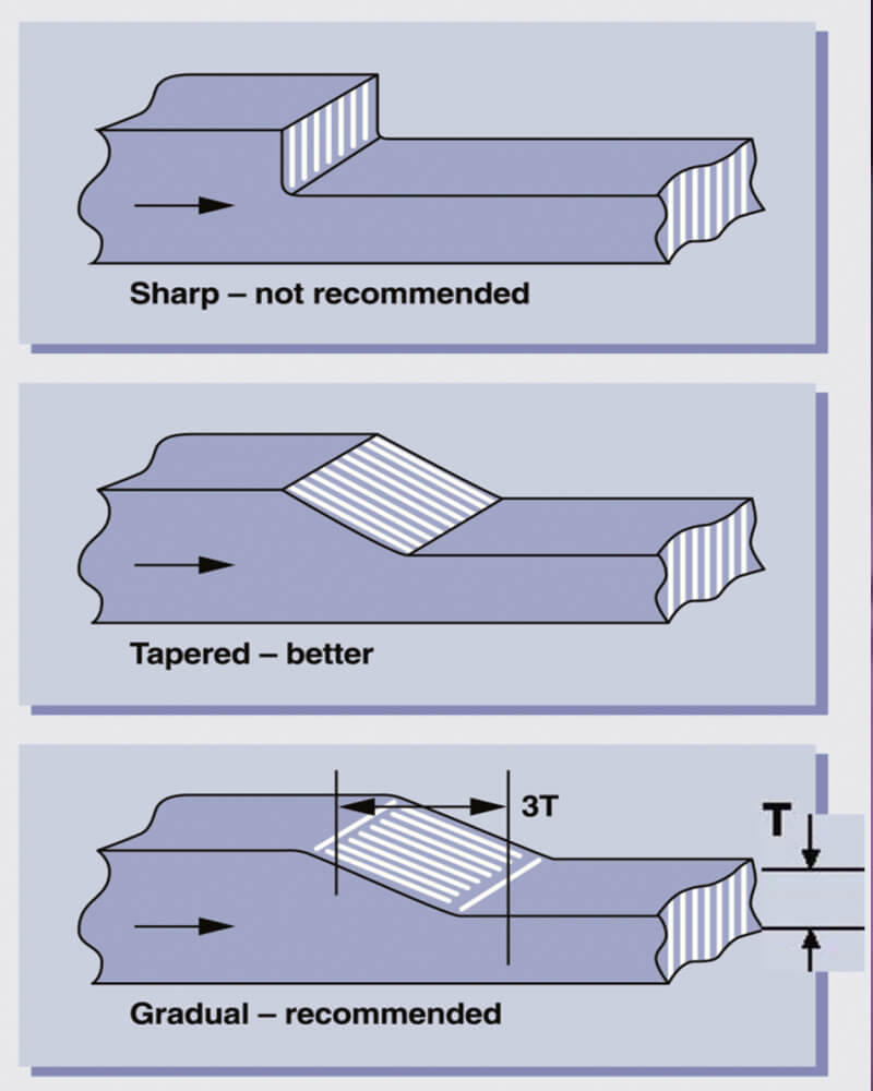
- Gradual transitions: If you need to change wall thickness, make sure the change is gradual and not abrupt. You can use gradual transitions (usually a 3:1 ratio) to prevent stress concentrations and ensure smooth material flow.
- Draft angle: Draft angle helps remove the part from the mold without damaging the part or the mold. For most materials,1-2 degrees of draft angle per side is sufficient, but thicker walls may require more draft angle to compensate for shrinkage and ensure smooth ejection.
Product functionality and requirements
The intended use of a part plays a critical role in wall thickness design:
- Strength and Stiffness: Parts that require high strength or stiffness may require thicker walls or strategic reinforcement with ribs or gussets.
- Flexibility and Impact Resistance: Certain applications require thinner, more flexible walls or specific materials to achieve the required impact resistance.
- Aesthetic Considerations: Wall thickness affects surface finish and can cause visual defects such as dents or flow lines. Balancing aesthetics with functionality is often necessary.
Mold design and process parameters
Mold design and process conditions have a significant impact on wall thickness decisions:
- Gating and venting: Design of the gating and venting system ensures uniform material distribution, which in some cases allows for thinner wall thicknesses. Select gate locations that promote uniform flow and minimize the risk of welding lines. Ensure adequate ventilation to allow trapped air to escape, reducing the risk of voids and burn marks.
- Injection pressure and speed: Higher pressures and speeds allow for thinner wall thicknesses to be filled but can introduce stresses or other defects if not properly controlled.
- Melt temperature: Higher temperatures improve flow but can increase cooling time and affect part performance.
- Mold cooling: An efficient cooling system allows for more consistent wall thicknesses and helps alleviate issues with thicker parts.
- Cycle time considerations: Thinner wall thickness allow for faster cooling and shorter cycle times, which improves production efficiency.
Simulation software and prototyping
Modern injection molding relies heavily on simulation tools and physical prototypes to optimize wall thickness:
The software predicts how the plastic will flow and cool within the mold, allowing designers to identify potential issues before tooling is created. By simulating various wall thickness scenarios, potential defects such as sink marks, warpage, or undercuts can be identified and addressed early in the design process.
Prototypes can be subjected to a variety of tests to evaluate strength, impact resistance, and other performance criteria. Techniques such as ultrasonic testing or cross-sectioning can be used to verify wall thickness consistency between prototypes and production parts.
Common wall thickness problems and solutions
Sink marks
Sink marks are depressions or dimples that appear on the surface of molded parts, typically opposite thick sections or at the base of ribs and bosses. Causes:
- Excessively thick wall sections
- Improper cooling, especially in thick areas
- High melt and mold temperatures
- Insufficient packing pressure
solutions
- Implement uniform wall thickness throughout the part
- Use coring techniques to reduce thick sections
- Design ribs at 50-70% of the main wall thickness
- Add texture to the part surface to mask minor sink marks
- Increase packing pressure and time
- Optimize cooling time and mold temperature
- Consider using materials with lower shrinkage rates
warp and deformation
Causes:
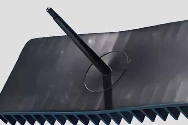
- Uneven wall thickness leading to differential cooling and shrinkage
- Asymmetrical part design
- Improper gate location
- Residual stresses due to processing conditions
Solutions
- Aim for symmetrical part design whenever possible
- Maintain uniform wall thickness throughout the part
- Use ribs or gussets to reinforce areas prone to warpage
- Balance mold cooling to ensure uniform temperature distribution
- Adjust injection speed and pressure to minimize internal stresses
- Optimize packing pressure and time
- Consider using a multi-gate system for large or complex parts
- Select materials with lower shrinkage rates or filled grades for improved dimensional stability
short shots and flow restrictions
Short shots occur when the mold cavity is not filled, resulting in incomplete parts. Flow restrictions can lead to short shots or other quality issues. Causes:
- Insufficient wall thickness, especially in areas far from the gate
- Improper gate location or size
- Inadequate venting
- Low injection pressure or speed
Solutions
- Increase wall thickness in critical areas, especially those far from the gate
- Optimize gate location and size to improve flow
- Increase injection pressure and speed
- Raise melt temperature to improve flow
- Ensure proper venting to allow air escape
- Consider using materials with higher melt flow indices for challenging geometries
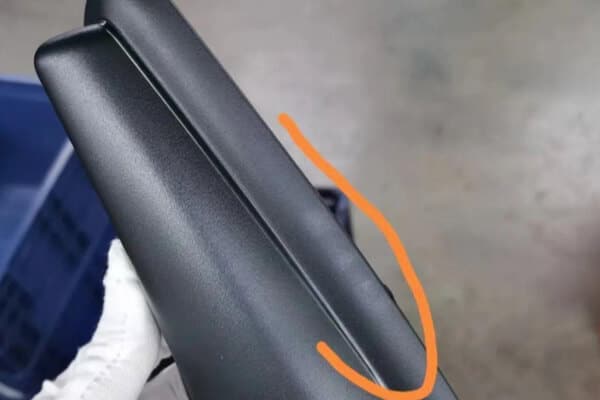
voids and air pockets
Voids are internal cavities or bubbles within the molded part, often caused by trapped air or gas. Causes:
- Insufficient venting
- Rapid cooling of thick sections
- Improper packing pressure or time
- Gas generation from material degradation
Solutions
- Implement uniform wall thickness to promote even cooling
- Add venting channels or improve existing venting
- Increase packing pressure and time
- Adjust cooling rate, especially for thick sections Optimize melt and mold temperatures
- Ensure proper material drying to prevent moisture-related voids
- Consider using degassing additives for materials prone to gas generation
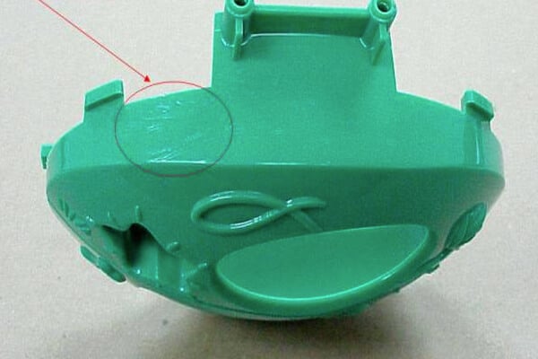
Flow lines
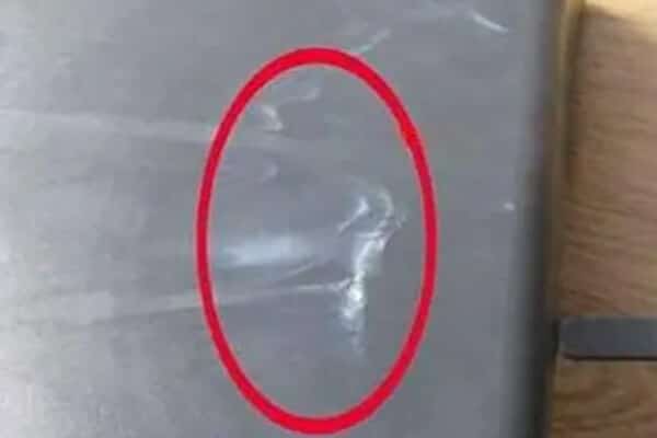
Flow lines are visible patterns on the part surface that indicate the path of material flow during injection. Causes:
- Abrupt changes in wall thickness
- Obstacles in the flow path
- Low melt temperature or injection speed
- Poor gate location
Solutions
- Ensure smooth transitions in wall thickness
- Optimize gate location to promote even flow
- Round corners and edges to improve flow
- Increase melt temperature to improve flow characteristics
- Optimize injection speed
- Consider materials with better flow properties for complex geometries
Partner with China's leading injection molding experts
At YUCO, we are at the forefront of injection molding technology, providing solutions to the most challenging wall thickness problems. Our experienced team of engineers and designers use advanced strategies to optimize your parts for improved performance, aesthetics, and cost-effectiveness.
Advanced wall thickness design strategies we use:
- Use variable wall thickness for specific products.
- Gas-assisted injection molding of thick sections with hollow cores.
- Use varied materials with different wall thicknesses in a single part.
- Optimize wall thickness to reduce material usage without compromising strength.
Contact YUCO today for a free consultation to learn how our innovative wall thickness design strategies can take your injection molded parts to new heights of quality and efficiency.
Tel: +86 13586040750