Injection molding is a high-quality process, but stress marks need to be avoided. Stress marks can affect the aesthetics, structural integrity, and performance of the finished product.
If not addressed, stress marks can lead to increased scrap rates, increased rework costs, and product returns. By avoiding stress marks, manufacturers can reduce the risk of defects, saving time and money overall.
Understanding the root causes of stress marks and implementing effective prevention strategies are essential to maintaining high-quality production standards. As a China-based injection molding service provider with extensive experience in precision manufacturing, we recognize that addressing this common defect is critical.
This comprehensive article will delve into the basic mechanisms behind stress mark formation, explore the various contributing factors (from material selection and process parameters to mold design considerations), and provide practical solutions to prevent or minimize these defects. Read on to learn more.
Understanding stress marks
What are stress marks?
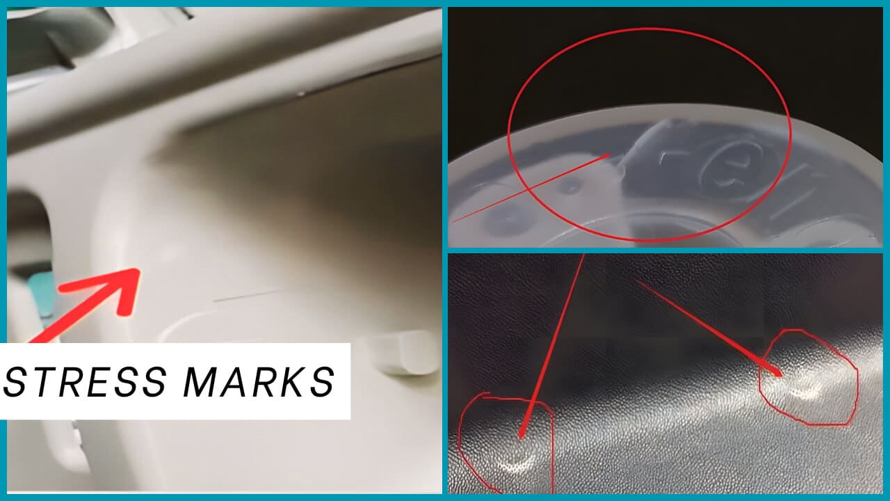
Stress marks (also known as stress whitening, stress cracking, or stress bleaching) are visual and structural defects that occur when localized stresses are excessive within a plastic material. Visually, these defects appear as white, cloudy, or translucent areas on the surface or within the plastic part. The appearance varies depending on the material, processing conditions, and stress severity. They typically appear in flow paths, near gates, corners, or areas with significant thickness changes.
Types of stress marks
Stress marks in injection molding can be divided into several different types based on their formation mechanism:
- Orientation stress marks: This type of stress mark occurs when polymer chains are overstretched and aligned in a specific direction during the filling phase of injection molding, such as when molten plastic flows through a restricted channel or thin section. Orientation stress marks usually appear as streaks or lines that follow the direction of material flow.
- Shear stress marks: Shear stress marks are caused by excessive shear rates during the injection molding process. These marks typically appear near gates, sharp corners, or anywhere the melt experiences rapid directional changes or restrictions. Visually, shear stress marks may appear as white bands or patches perpendicular to the direction of flow.
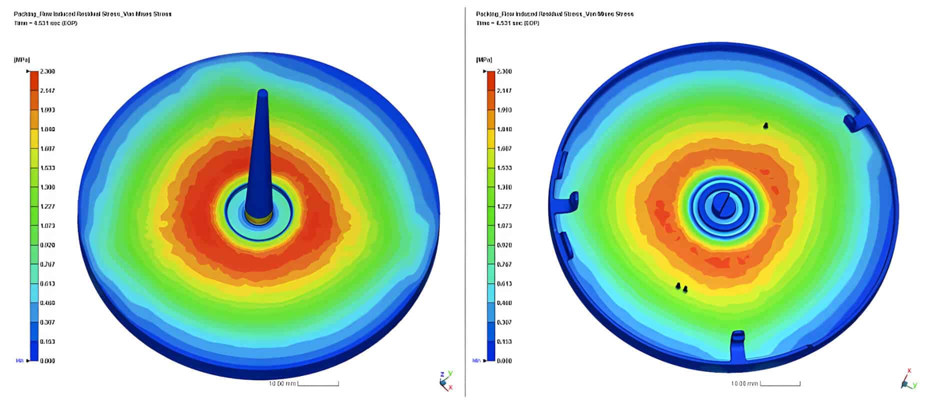
- Residual stress marks: Residual stress marks form during the cooling and solidification phases. They are caused by uneven cooling rates and differential shrinkage throughout the part. These marks typically appear as diffuse, cloud-like areas and may not be immediately apparent until the part is fully cooled or even days after it is formed.
Causes and solutions for injection molding stress marks
The formation of stress marks in injection molded parts is influenced by a complex interaction of multiple factors. Successful prevention of stress marks requires a comprehensive approach that addresses multiple aspects of the injection molding process. Let’s look at the four main categories of factors that contribute to the formation of stress marks. Then, by implementing these strategies in a targeted manner, manufacturers can significantly reduce or eliminate stress marks, resulting in higher quality parts with improved appearance and mechanical properties.
Material selection
The inherent properties of polymer materials play a fundamental role in the formation of stress marks. Careful material selection can avoid injection molding stress marks.
- Coefficient of thermal expansion (CTE): Select materials with a lower CTE to reduce internal stresses that can cause stress marks. For example, polypropylene or ABS have a lower CTE, so they are less prone to stress marks than materials with higher CTEs, such as polycarbonate or acrylic.
- Stiffness: Strong nylon and other materials with higher stiffness can generate internal stresses that cause stress marks if the material does not minimize the accumulation of tension. Selecting materials with lower stiffness, such as polypropylene or ABS, can help reduce the risk of such stress marks.
- Chemical resistance: Consider the chemical environment your part will be exposed to and select materials with the best chemical resistance for that environment. Materials that resist exposure can degrade due to improper maintenance and become more susceptible to stress marks.
- Molecular structure: Amorphous polymers such as polycarbonate (PC), polystyrene (PS) and acrylic (PMMA) generally show more visible stress marks than semi-crystalline polymers such as polyethylene (PE) or polypropylene (PP). This is primarily due to the greater optical clarity of amorphous materials, which makes any internal stresses more apparent. Consider modified grades of PC, PMMA or other clear polymers specifically formulated to reduce stress marks
- Moisture content: Excessive moisture in hygroscopic polymers such as ABS, PC, PA or PET can lead to hydrolytic degradation during processing, which reduces molecular weight and changes flow behavior. This degradation not only weakens the material, but also creates inconsistent flow patterns, which can lead to stress concentrations. Proper material preparation before processing is important; even the most suitable polymers can produce stress marks if not properly prepared.
- Additives: Various additives in polymer formulations can significantly affect the appearance of stress marks. Processing aids that improve flow characteristics without increasing orientation are recommended. The following are common additives: 1. Fillers (glass fibers, minerals) can restrict polymer chain mobility and thus may increase residual stress. 2. Nucleating agents in semi-crystalline polymers can affect the crystallization rate and subsequent stress distribution. 3. Plasticizers generally reduce the formation of stress marks by increasing chain mobility and reducing melt viscosity
Process parameters
Fine-tuning injection molding process variables is critical to minimizing stress mark formation.
- Injection speed: Too high an injection speed can create considerable shear stresses as the material flows through gates, runners, and thin-walled sections. Conversely, too slow a speed can cause premature cooling and create a high-stress flow pattern as viscosity increases during filling. Instead of using a constant injection speed, implement a curve-controlled approach. Start with a moderate speed to establish flow, and reduce speeds to minimize shear when filling thin sections or complex features. Consider using sequential valve gates for large or complex parts to control flow front advancement
- Injection pressure: High injection pressures force material into the mold cavity at a rate that creates excessive stresses. While adequate pressure is necessary for complete filling, too much pressure can unnaturally compress the material, creating residual stresses that remain after the part cools. Modern molding processes often employ pressure curves to optimize filling while minimizing stresses.
- Melt temperature: Too low a melt temperature can increase viscosity, require higher injection pressures, and create greater shear stresses during filling. Too high a melt temperature may reduce viscosity, but it can degrade the polymer, affecting its molecular structure and stress response. Inconsistent melt temperatures can create areas of different flow behavior, leading to local stress concentrations. It is recommended to increase the melt temperature appropriately, but not beyond the material specification range
- Mold temperature: A cold mold causes the material in contact with the mold surface to solidify quickly, while the core remains molten, forming a “frozen skin”. Uneven mold temperatures in different parts can lead to different cooling rates and uneven stress distribution. It is recommended to implement mold temperature control zones to keep the surface temperature of different parts of the part consistent. Alternatively, it is appropriate to use higher mold temperatures to slow solidification and allow more time for stress relaxation
- Pack pressure and time: During the packing phase, as the part cools, additional material is forced into the mold to compensate for shrinkage. Insufficient packing pressure cannot fully compensate for shrinkage, resulting in internal void concentration stress. Excessive packing pressure can over-compress the material and produce residual stress. It is recommended to use sufficient packing pressure to ensure appropriate part density and extend the packing time to more completely release stress before the gate freezes. Consider decreasing contour packing pressure to minimize pressure gradients
- Cooling time: Rapid cooling can “lock” the molecular orientation before the polymer chains relax to their preferred state. Insufficient cooling time can cause part distortion after ejection. Uneven cooling can cause differential shrinkage and stress concentrations. Properly control cooling, such as increasing cooling time, using a conformal cooling system for complex part geometries, or implementing a stepped cooling profile
Mold design factors
The design and construction of injection molds have a profound impact on the formation of stress marks, and a well-designed mold can significantly reduce the formation of stress marks.
Gate location and size
The gate controls how the polymer enters the cavity and significantly affects the formation of stress marks. A gate size that is too small will produce excessive shear as the material squeezes through, resulting in a stress mark area immediately around the gate. An unbalanced multi-gate system will cause inconsistent filling patterns and pressure variations, which can cause localized stresses.
Position the gates to create a balanced flow path and use multiple gates for large parts to reduce flow length and direction. Also consider using fan gates or film gates for wide parts or implementing sequential valve gates to control the filling order of complex parts.
Runner system design
The runner system delivers molten plastic from the injection unit to the mold cavity.
Inefficient runner design will produce pressure drops, resulting in inconsistent filling and holding pressure. Size the runners appropriately and use full-round runners whenever possible to minimize pressure losses and material shear.
For multi-cavity molds, design naturally balanced runners to ensure uniform filling. Consider using a hot runner system, if necessary, to achieve consistent melt delivery without the cooling effect of a cold runner
Venting design
Inadequate venting can trap air, which compresses under pressure and then expands as pressure drops, creating localized stresses.
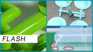
Strategically placed vents help ensure uniform filling and pressure distribution, reducing the formation of stress marks. Properly size the vents (typically 0.025-0.040 mm deep for most plastics) to allow air to escape without flashing material. Consider using vacuum-assisted venting or incorporating degassing into the runner system, if necessary, for materials susceptible to moisture or volatile release.
Part design considerations
Part design flaws can create internal stresses within a part, which can cause stress marks. By considering these design factors, manufacturers can optimize part design to reduce the risk of internal stresses and stress marks, resulting in high-quality injection molded products.
- Wall thickness: Uneven wall thickness creates different cooling rates and uneven shrinkage, while the transition from thick to thin sections can force the polymer to accelerate, increasing orientation and shear stresses. Designing parts with uniform wall thickness can help reduce the risk of stress marks. Industry best practices recommend gradual transitions between different wall thicknesses (usually no more than 25% change per 3 mm flow length)
- Avoid sharp corners and edges: Sharp corners and edges create stress concentrations where polymer chains can become highly oriented. Designing parts with rounded corners and edges can help distribute internal stress more evenly, reducing the risk of stress marks.
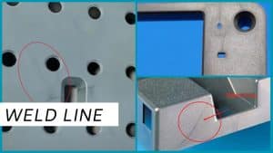
- Weld lines: Weld lines are where two streams of molten plastic meet and bond, creating internal stresses. To reduce the likelihood of stress marks, design parts with as few weld lines as possible or place them in discrete locations.
- Draft angle: Draft angles are slight angles built into the part wall to facilitate ejection from the mold. Insufficient draft may require excessive ejection force, creating stress when the part is removed. Inconsistent draft angles create uneven ejection forces, which can cause localized stresses. Properly designed draft not only aids ejection, but also allows for more even cooling and stress distribution. Textured surfaces often require larger draft angles to prevent surface damage and stress during ejection
- Reinforcement: To reduce the risk of stress marks, consider adding reinforcements to your design, such as ribs or gussets, to evenly distribute pressure and prevent internal pressure.
- Radius and fillet optimization: Well-designed curve transitions can reduce stress concentrations, such as large radii at corners and intersections (minimum radius is approximately 25% of wall thickness) and fillets at the base of vertical features such as ribs or bosses.
Timely detection and measurement
Manufacturers must implement stringent quality assurance measures to quickly detect and correct stress mark problems.
Visual inspection can identify stress marks, looking for unusual lines or streaks on the surface. A magnifying glass and good lighting are helpful inspection tools.
For more precise analysis, specialized imaging techniques can be used, a common method is photoelastic stress analysis using polarized light to visualize stress patterns.
There are also stress measurement tools that provide objective data for process control.
Remedial techniques
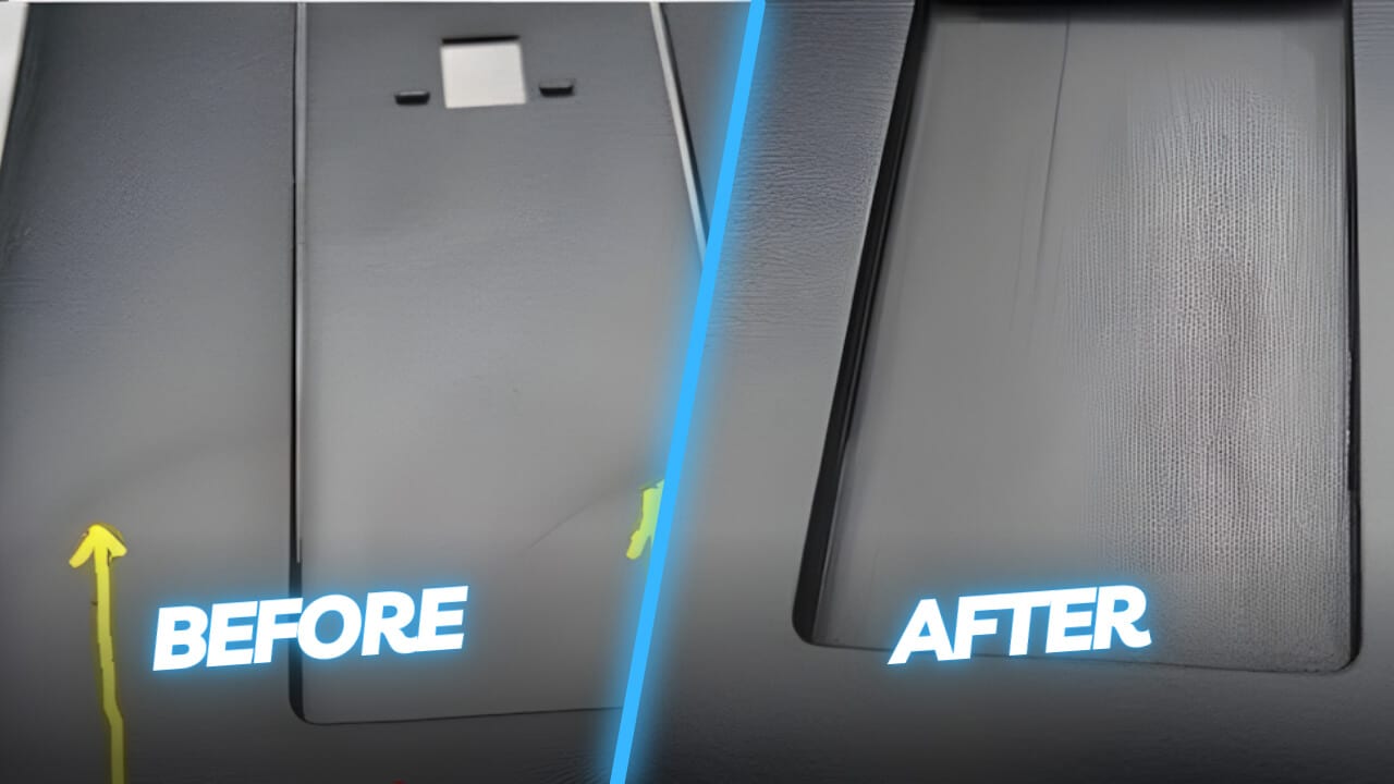
When stress marks cannot be completely prevented through process and design optimization, remedial treatments can help. Minor stress marks can be repaired through several post-processing techniques listed below, but large marks may require redesigning the mold or adjusting the manufacturing process to achieve better quality.
- Solvent vapor polishing of amorphous plastics such as PC, ABS, or PMMA
- Heat treatment using infrared or convection methods to promote stress relaxation
- Mechanical polishing or grinding to reduce surface stress marks
- Using annealing processes, controlled heating below the melting point of the material can relax internal stresses
- Using surface treatments, various coatings can mask or minimize the appearance of stress marks
Conclusion
In high-precision applications in the automotive, medical, consumer electronics, and optical industries, even minor stress concentrations can lead to premature product failure, loss of optical clarity, or reduced surface quality. Designers and manufacturers should avoid stress marks to produce high-quality injection molded products.
Partner with YUCO MOLD to create stress-free injection molded parts.
As a leading injection molding service provider headquartered in China, we have spent years perfecting our injection molding methods.
Material expertise: Our material experts work with you to select the best polymer formulation for your specific application, taking into account performance requirements and stress mark resistance.
- Advanced process control: We precisely control every process parameter that is critical to preventing stress marks.
- Design for manufacturability: Our experienced engineering team provides valuable input during the design phase to identify and resolve potential stress mark issues before the mold is built.
- Quality assurance: We use a comprehensive part inspection approach, including advanced optical technology specifically designed to detect subtle stress marks.
Contact us today to take advantage of our technical capabilities. We provide world-class molding services at highly competitive prices without compromising quality.

